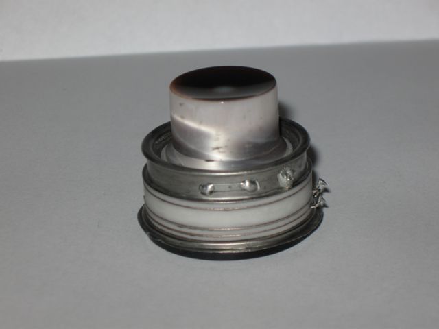
Gen3 Image intensifier encased in a clear elastomer compound showing internal components.
AUNV-TEMPORARY-FORUM
[ main ][ links ][ about ][ help ][ discussions ][ projects ]Image Intensifier Operation and Performance – What would make it better? Pictures included.
Welcome to November's article about Tube Performance and some questions then for the readers – These questions are about the tube itself ( though I've posted them separately in a thread here: ) and the below article examines the performance factors for image tubes outside of the constraints of the monocular or night-vision scope. The questions aren't obligatory, but I'm hoping everyone can participate as I'm collecting the responses and providing them to a night vision manufacturer to help them understand what new features their customers would like to see. As such, this is a valuable opportunity for forum members to help influence the future of night vision development. Participation is voluntary and anyone wanting to PM or email me directly is welcome to do so -
This article is specifically about the Image Intensifier tube, and possible future development of this technology.
Image Intensifier technology has progressed far more rapidly than the housings it sits within. While modern PVS-14's have very little different to the early PVS-5's, the intensifier within has undergone generations of changes and has also born significant improvement with every new iteration of the updated technology.
![]()
Gen3
Image intensifier encased in a clear elastomer compound showing
internal components.
There are a number of factors that affect tube performance, which are common to all image tubes however – what affected a Gen2 still equally affects a Gen3. Techniques and technologies for both are still improving, yet what works well for one can often be applied to the other.
This month's series of questions are based around tube technology – and given an equal platform, look at what makes the difference between a good system and a great system.
This is possibly demonstrated by the venerable PVS-14. Originally developed in 1998, it's proven to be the AR15 of night vision devices, fulfilling roles as diverse as a rifle-mounted device and a camera-attachment, even though it's primarily intended as a head mounted unit. Throughout it's service lifetime – over fifteen years – it's performed admirably and is still the standard against which all monoculars are measured, with no sign of it being replaced soon despite advances in technology throughout this period.
It would be too easy to think of it as a single monocular however, with equal performance throughout it's lifetime. Despite it being post-Omni IV however, a number of improvements – some of great significance, have occurred throughout it's lifetime, on both the gain-controlled and fixed-gain models and derivatives.
A Photonis XR5 Super-S25 Photocathode image tube depotted and cleaned
for repair.
To understand the questions, I'll discuss those technology leaps and how a change in tube technology can deliver a huge improvement in performance.
The basics of an image tube haven't really changed since WW1, and of Gen2/3 tubes since the Vietnam war.

The photocathode works like a solar panel, converting photons to electrons, except that instead of moving through a wire to provide power, they are pulled across a vacuum by a high-intensity electrostatic field. When these electrons hit a screen, they are converted back into light, allowing us to see the image that created them. With appropriate inclusion of internal amplifiers that either multiply the number of electrons or increase their kinetic energy, this image can be made brighter than the image which created it. This process forms the basis for all image intensifier tubes.
While it's easy to think of Gen2 and Gen3 tubes as fundamentally different due to the composition of their photocathode, this is only true in one sense. In all other ways, both Gen2 and Gen3 systems share the same functional operation of the Photocathode, which is the heart of the Image Intensifier.
What does vary between photocathodes however than makes a difference is the spectral sensitivity and efficiency that defines how well a photocathode will convert different colors of the visible and infrared spectrum into electrons.
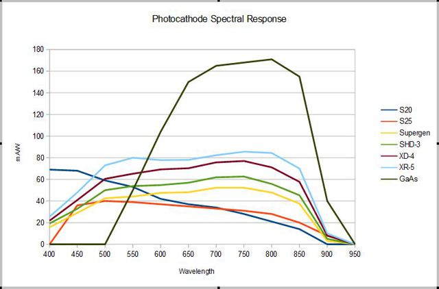
A basic chart showing the different spectral response of common
photocathodes.
Under extreme low light, it's usually considered that the most sensitive photocathode is the ideal photocathode, and while it's usually true, other factors come into play. GaAs is very sensitive, but lacks response below blue in the spectral range, and is more affected by dark current than alkali metal tubes. Although it's not shown, AgO ( Silver Oxide ) or S1 was the first photocathode discovered and is still one of the most sensitive photocathodes for most purposes above 1000nm, but has very poor response across it's entire spectral range.
Even when considering the more sensitive range of photocathodes, the availability of light is important. Gen3 is more sensitive to 940nm LED produced light than any of the Gen2 photocathodes, and works extremely well with illumination. Gen2 ( and the Super-Gen2 ) S25 photocathodes give excellent response across the spectrum, sometimes allowing better contrast of items, so that they more closely match a monochrome image of what we see with our eyes. S20 is still the best photocathode for spotting corona-discharge or hot-spots from fires, and under such purposes, a simple Gen1 S20 scope is far more effective than the best ( or worst ) of Gen3 scopes.
The spectral distribution of the light source is also very important, as is the albedo of the environment with respect to that spectral distribution. Dry and dead vegetation provides less IR reflectivity than does green plant material. Starlight is similar to sunlight and moonlight, but skyglow is more prominent above 800nm and significantly so above 1100nm, peaking at 1400nm.
All of this is moot however, without contrast. Even a low-signal high-contrast image can be easier to make out than a high-signal low-contrast image.
Ion barriers are attached to the input surface of the MCP and are intended to extend tube life by blocking damaging positive ions from striking the photocathode. It's primarily used in Gen3 systems, as GaAs photocathodes are more prone to ion damage than alkali metal photocathodes. Aside from tube life however, it provides no positive benefit to the tube function. It's presence increases noise, reduces signal and if it's incomplete ( it can have holes in it ) then it can cause visible patterns on the image also.
From a technical perspective, the loss of signal across the ion barrier is know as it's “dead voltage”.
Holes in the ion barrier are permissable. According to Omni VIII,
1
Ion barrier film quality (if necessary). There shall be no more than 10 type-B holes over the total useful area of the output screen. There shall be no more holes present with an effective diameter greater than 125 micrometers.
25 micrometers ( micron ) is about 1/8th
of the diameter of a halo ( see next section ).
Filmless tubes ( Most Gen2 and Gen3 filmless ) do not require an Ion Barrier. In the case of Gen3 tubes, the autogating is modified to cause the ions that have buried themselves within the photocathode to tunnel their way back out before permanent damage from ion poisoning occurs.
Because of the Ion Barrier, there is an effective limit to how low the voltage can be between the Photocathode and the MCP – this too can affect the spacing options between the parts and also the halo size.
The MCP provides the majority of the gain inside a modern image tube, but it also has a few side effects. The first is that it adds noise in terms of the amplification – especially when saturation approaches. The second is that it also causes an obvious halo, which is seen as a lighter area around bright spots when viewed through a monocular.
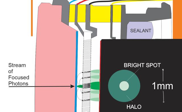
Magnified cross-section of tube showing effect of electron “spray” from a bright spot.
Additionally, even though the electrons coming from the MCP might be hitting a small area a few microns across, the electrons spray out of the photocathode in a cone-shaped stream and likewise, also similarly spray from the MCP.
Halos occur before the MCP amplification stage, due to electrons missing the microchannel holes and bouncing off to strike elsewhere on the MCP, each causing a visible mark.
When enough electrons are present, from a bright spot when viewed, this has two effects. The first is that the apparent size of the bright spot appears larger. The second is that is has a highly visible round halo surrounding it, bordering the bright spot.
Generally, Halos are in the order of 0.6 to 1.0 mm in diameter, but on an 18mm wide screen, that's significant.
Halos are always present, even when not visible, and add to the noise that competes with the signal to lower the overall tube S/N ratio and damage the tube's MTF or Modulation Transfer Function.
Halo's can be reduced by varying the surface that they strike before entering the MCP ( either the MCP face or the aluminium-oxide film in filmed tubes ), reducing the flat surface (ie, increasing hole diameter ) and the size of the bright spot caused by spray can be reduced by increasing the voltage across the vacuum.
One of the effects of the MCP/Photocathode spacing is that the halo size is directly proportional to the distance between them – with the halo approximately four times larger than the spacing – which with a tube of around 0.8mm halo means around 0.2mm spacing.
Because the MCP is very thin, and can flex under high levels of acceleration, such as when mounted in a rifle-attached NOD, it can impact the photocathode. As such, recoil resistance is a factor that is required to be engineered into the tube. Most tubes have recoil ratings of 75 G's, though many tubes with larger halos or intended for weapon use can withstand levels of around 500 G's. Some Gen2 tubes with halo's smaller than 0.8mm are, however, rated at > 700 G's.
At the ocular-end of the intensifier, is the phosphor screen. It is here that the image is converted back from electrons to photons for our eyes to perceive. At this point, all color information within the tube is lost and so all screens are a single color. Phosphor screens have been around for well over a century, but only a few phosphors are used for night vision purposes.
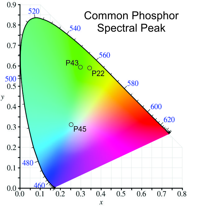
Spectral distribution of common phosphors
Green is the most common, as this is where the eye is naturally most sensitive – especially under very dark conditions. It is for this reason that most night vision screens are green. However even here, there is a range of effects – some night vision is deep green ( P22 ) while others are a yellowish-green ( P43 ). Some have a blueish tinge and more recently, white phosphor ( P45 ) is increasing in popularity, usually for reasons of reducing fatigue.
The current Omni VIII specification defines P43 for US night vision, as are most recent foreign phosphor milspecs, but even then, this has not limited the inclusion of other options.
However, it's not just the color that's important for NV purposes, but the decay time and brightness of the phosphor – A fast phosphor will update quickly and be less likely to “streak” than a slower one, but generally is not as bright. Additionally, during low-light viewing, the image can appear to break up into something that more resembles snow as our persistence of vision is not sufficient to allow the image to be fully reconstructed in our brains.
P22 has a slower decay time of around 60ms (10%) and a broader spectral curve and is quite bright, making it very popular in Gen1 and Gen2 night vision, however it's not as responsive as P43 (1.2ms) and P45 (1.7ms).
The final factors affecting the image are noise factors introduced by the intensifier itself. These are visual artifacts that interfere with our ability to perceive the image being presented to us.
This includes physical artifacts such as fixed pattern noise, which often originates from manufacture, and includes black spots where the intensifier doesn't provide an image (usually small ) - and sometimes a honeycomb-like pattern that is caused by the joins between fiber bundles that are common in intensifiers that have fiber plate inputs or outputs.
These blemishes are present in all image intensifiers, however are not always visible, or may be very small in relation to the image size such that they are easily ignored.
Blemishes or spots can also be caused by damage, from over-bright light exposure such as laser damage, and sometimes from internal faults that cause later damage, such as emission points. Emission points too cause problems with the image as they appear as a very bright point of light until they grow or burn out, and are also a sign of tube faults.
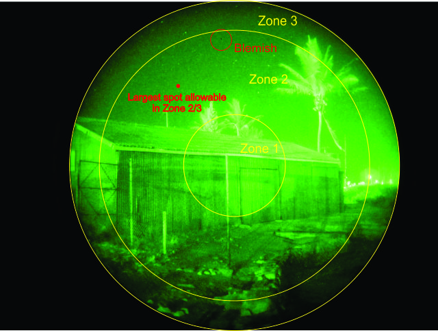
An
image showing a typical spot, how it affects the image, and how large
it can be under Omni VIII.
Dynamic noise is also present, from signal-related noise caused by the MCP, to brief bright spots caused by ion-strikes on the photocathode, and also low-level signal which, due to the lack of visible photon strikes, is not integrated by out persistence-of-vision and so appears to our eyes as noise.
Depending on manufacture, other problems can exist. Off-axis construction can render the image we see appearing to be at a different angle – this can cause eyestrain, especially when two intensifiers are used in a binocular system.
Distortion to the image can equally be an issue, causing straight lines to appear to bend, especially at the edge of the image.
Even dark-current induced noise ( EBI ) can appear to wash-out an image in warmer environments, leading to significant increases in the perceived brightness of areas that should be dark – this too can make it difficult to peer into truly dark areas.
Although Military intensifiers have stringent control requirements, there is always some permissible level of each of these problems, except emission points, which are considered a sign of a faulty tube. Some, such as off-axis alignment, can cause significant issues when both eyes are used, resulting in visual problems – even within the acceptable limits of the tube. This is especially the case with MX11769 tubes, such as are found in the AN/PVS-14.
Overall, these too affect the use and effectiveness of the image intensifier.
While the above information was somewhat verging on the technical, the suitability of an image intensifier for a particular purpose often comes down to user needs – in fact a great deal of it comes from either learning to use the intensifier to it's best, or from finding what is most comfortable to the user.
This is most commonly demonstrated by the different gain levels selected by users of night vision on gain-control systems. People new to night vision often turn the gain up as far as possible, trying to make up for what they can no longer see, however veteran users frequently turn the gain down, realizing that with gain comes noise, especially from the MCP, and a lower setting may provide the better contrast that allows the necessary detail to be seen. To this extent, looking through a good image intensifier is often described as being like Looking through a sheet of green glass.
Ultimately, an image intensifier should provide a comfortable image, have as little noise as possible. Many people covet blemish-free units, while others see them as a cheap and convenient source of low-cost night vision.
Because the image intensifier is affected by so many factors, they cannot be selected on any one criteria, but rather must be selected as a whole. Indeed, no one factor affects resolution and MTF ( Modulation Transfer Function ) - however these are two criteria by which image intensifiers are often selected.
Older comparative metrics, such as the “FOM” or “Figure Of Merit” - obtained by multiplying the MTF by the resolution, only provide a quick method of calculating effective range of a NOD, but ignore whether or not the NOD is sufficient in other areas.
Although image intensifiers haven't changed a lot over the past 15 years, they have changed, and the improvements are notable. Sharper, Clearer, Less Noise. Each new iteration of technology makes small but noticeable improvement on the last.
And finally, even within a batch, image intensifiers aren't equal, but often follow a bell curve through which some are poor, some are good, many are as designed and some are exceptional.
But regardless, one thing is certain – beauty is in the eye of the beholder – and more so when it's being viewed through a night vision monocular.
So what does the future of NV hold? Where can image intensifiers go in a world in which we're already fusing the image with other sensors? What could be better? Some food for though.
Hybrids.
Hybrid image intensifiers are ones that combine multiple technologies. These are often known as something PLUS something else – eg, Gen 2+1 tubes combine a Gen2 and a Gen1 tube. This provides for very high gain with low noise that allows better performance than a simple Gen2 tube of similar photocathode and MCP could provide.
Digital Hybrid
Digital hybrids are likely to be more common in the future. A digital hybrid combines an image tube with an imaging sensor, a digital screen and image processing. This also allows image information to come from outside of the tube for integration into the view field. Digital systems would have similar benefits to hybrids, but would typically feature a rectangular field of view.
Digital hybrids might also allow features such as refocal processing, allowing increased depth-of-field – perhaps even infinite depth of field – across image screen zones. This would allow drivers to both see the distant road and the instrument panel in focus. Maps could be read easily and there would no longer be a need to have a lens that could be focussed.
Other signal processing possibilities could be added – perhaps embedding the map, with a GPS, into the NOD itself, eliminating the need to view maps in the first place. Edge and movement detection might provide additional tactical benefit.
Selective Availability and On-the-fly reprogramming.
Early power supplies were mostly simple circuits, including an oscillator and some protective feedback loops. Recently, they've been replaced by computer controlled digital systems that allow reprogramming of the tube function, from adjustable MTF for export to variable maximum and minimum gain levels. Typically these are programmed through the gain control lead or, in more recent iterations, an infrared communications port on the power supply.
Information can also be transferred to the image tube power supply through baseband, via modulation of a brighter source through the image itself. Such process may be used in the future to turn off enemy intensifiers, but could also be used to reprogram individual units. Likewise, an alternative baseband interface could be via the power supply input, via modulated signal – such would also be useful for digital hybrids as it could be a method of providing input for fused and combinational displays, while providing backwards compatibility.
Simple Enhancements.
Even without the futuristic speculative possibilities, some enhancements can still be achieved with classic image intensifier architecture. 64 lp/mm might provide near-retina-display like angular density, but it's only a 3% MTF. Improvements in the resolution and MTF of a tube would provide a significant advantage.
Contrast enhancement can come from improvement of the spectral response the of photocathode, or improve sensitivity in different regions of the spectral response.
Many tubes are still weak in high light environments and the period during dawn and dusk when they are still tactically advantageous is another area that improvement is constantly being made. Autogating is a relatively new technology, even amongst current generation tubes – only really being standard since Omni VII.